
Efficiency and Thermal Management in DC-DC Converters
When choosing a DC-DC converter, most engineers look first at the output power; however, two critical factors that determine a power module's true performance and field life are efficiency and thermal management. As efficiency decreases, the power consumed by the module is converted to heat, causing the temperature to rise, the component life to shorten, and system reliability to decrease. In this article, we examine the engineering aspects of where efficiency comes from in DC-DC converters, the physical sources of losses, thermal management strategies, and how to properly size a module from a thermal perspective. Our goal is to provide an engineering perspective that allows you to read the table behind the single "92% efficiency" line on the data sheet.
What is efficiency in a DC-DC converter, and why is it critical?
Efficiency (η) is the ratio of output power to input power: η = P_output / P_input. The difference between the two is the power loss that is converted to heat within the module (P_loss = P_input - P_output). This simple equation explains why a small difference in efficiency can result in large effects on the field side. For example, if a module with 100 W of output operates at 95% efficiency, it generates approximately 5.3 W of heat; if the same module operated at 88% efficiency, the value would be 13.6 W. So a 7-point loss in efficiency increases the heat to be dissipated by more than two and a half times.
This difference is important in three aspects. First thermal: more loss means a larger heat sink, a more powerful fan or a wider copper area. Second reliability: the life of semiconductors and electrolytic capacitors decreases exponentially with temperature; as a general rule, every 10 °C increase in core temperature roughly halves the capacitor life. Third operating cost: in industrial systems operating 24/7, efficiency directly affects the electricity bill. The DC-DC Converter category, which includes industrial modules with a wide input range, is a good starting point for evaluating these three criteria together.
Where do losses come from in DC-DC converters?
To properly manage total loss, it must first be broken down into its components. In a switch-mode DC-DC converter, losses can be broadly categorized into four groups.
- Conduction losses: The MOSFET's R_DS(on) resistance, synchronous rectifier, and inductor DC resistance, where power is dissipated as I²R. As the load increases, it grows with the square of the current, becoming dominant at full load.
- Switching losses: Occur during the brief transition periods when the transistor is turning on or off, and both voltage and current are present. It is directly proportional to the switching frequency; higher frequency provides smaller magnetic components but increases switching loss.
- Magnetic (core) losses: Hysteresis and eddy current losses in the transformer and coil core. Increases with frequency and current density.
- Idle/drive losses: Power consumed by the control IC, gate drive, snubbers, and auxiliary circuits. This is the main factor that lowers the efficiency curve at light load.
This distribution explains why the efficiency curve is shaped like a bell: efficiency is low at very light load because fixed losses predominate, peaks at medium load, and I²R losses rise again as the load approaches full. Therefore, it is not ideal to operate a module always below or at the very limit of its nominal power; it is healthier to design it to operate near the peak of the efficiency curve.
 Artesyn RFB300-24S12-R5Y In high-power isolated modules like this one, efficiency is the key to thermal design.
How is efficiency and power loss calculated?
The basis of thermal sizing is to determine the actual amount of heat that the module must dissipate. A practical approach is as follows: first, read the efficiency at your operating point (input voltage and load current) from the data sheet curve; then calculate the power loss.
P_loss = P_output × (1 − η) / η, where P_loss is the loss directly given when only the output power and efficiency are known. For example, if a module with a 12 V/25 A (300 W) output operates at 91% efficiency, the loss power is approximately 300 × (1 − 0.91) / 0.91 ≈ 29.7 W. This is the heat that your cooling system must dissipate; not the output power.
Once you have calculated this loss power, you can estimate the thermal rise: ΔT = P_loss × R_θ, where R_θ is the thermal resistance (°C/W) from the module's data sheet or from the choice of heatsink. The following table compares the heat generated by different efficiency levels for a reference output of 100 W.
| Efficiency (η) | Wasted power (at 100 W output) | Thermal load | Typical result |
|---|---|---|---|
| 98% | ~2.0 W | Very low | Passive cooling is usually sufficient |
| 94% | ~6.4 W | Low | Small cooler/copper area |
| 90% | ~11.1 W | Medium | Cooler, fan optional in most cases |
| 85% | ~17.6 W | High | Cooler + forced air flow |
| 80% | ~25.0 W | Very high | Powerful cooler and active cooling |
The message from the table is clear: a few percentage point improvement in efficiency reduces the complexity and cost of the cooling design. Therefore, a high-efficiency module is often more economical in total system cost, even if the initial price is slightly higher.
Heat management methods in a power module
After calculating the loss power, the next step is to keep it within safe limits. Heat management proceeds through three main mechanisms: conduction, convection, and radiation. In practical design, the first two are most commonly used.
Passive cooling and PCB design
In low- and medium-loss modules, the first line of defense is the printed circuit board itself. Large copper casting areas, thermal via arrays, and the copper heat sink placed underneath the module distribute heat across the board surface, allowing it to be dissipated through natural convection. In baseplate modules, this plate is a critical interface for transferring heat to the chassis or heatsink; adding a high-quality thermal interface material (TIM) eliminates the thermal resistance created by air gaps.
Active cooling and heatsink selection
As power loss increases, heat sinks and forced airflow become necessary. The key parameter here is the thermal resistance of the heat sink (°C/W): the lower it is, the smaller the temperature increase will be for the same power loss. Increasing the air speed (fan) significantly reduces the effective thermal resistance of the heat sink. At this point, planning EMI filters and thermal solutions together to facilitate system integration saves time in terms of both thermal and electromagnetic compatibility.
These approaches can be seen in industrial module families. For example, the Astec ASA00BB18-L and Astec ASA00CC18-L modules are designed for high-power-density operation by coupling their baseplates to a heatsink. All solutions of this type can be evaluated under the Astec brand portfolio.
 In module bases, the baseplate is the primary heat path that transfers heat to the heat sink.
How do I size the correct module?
A selection process that addresses both efficiency and heat management is the foundation of a system that works smoothly in the field. A practical checklist includes the following steps:
- Determine the actual operating point. Not the nominal power, but based on your continuous load and input voltage range, read the efficiency curve for this point.
- Calculate the loss power. Find the heat to be dissipated with P_loss = P_output × (1 − η) / η.
- Consider ambient temperature and derating. The derating curve on the data sheet requires you to reduce the module's output power above a specific ambient temperature. Do not rely on the rated value at 25 °C; size your system according to your site's hottest scenario.
- Select the thermal interface and heatsink. Convert the desired thermal resistance to the target surface temperature using the relationship ΔT = P_loss × R_θ.
- Leave a safety margin. Adding a 20-30% margin to the calculated continuous power extends the life and provides resistance to transient load increases.
Wide-input range and high-efficiency options can be evaluated among BEL Power Solutions 0RSB-50R080 modules, which offer flexibility in terms of derating and thermal headroom. For those who want to compare by brand, BEL Power Solutions and Artesyn pages make it easy to see different power and isolation options in the same family together.
 The efficiency curve in wide input range modules varies according to the operating input voltage; BEL Power 0RSB-50R080 is a good example in this regard.
Frequently Asked Questions
Does high efficiency in a DC-DC converter always mean less heat?
Yes, it is directly related. As efficiency increases, the loss power decreases and the heat that the module must produce and dissipate decreases. However, the ability to actually dissipate the heat into the environment still depends on the correct cooler, thermal interface, and air flow; high efficiency alone does not save a poor thermal mounting.
Why should I read the module's efficiency curve at the operating point, not at full load?
Because efficiency varies with load and usually peaks around medium load. If your system mostly operates at 40-60% load, using the efficiency at that point instead of the full load efficiency allows for a much more accurate calculation of the loss power and thermal design.
What is derating and how does it affect thermal management?
Derating is the requirement to reduce the safe output power of the module when the ambient temperature exceeds a certain threshold. The derating curve on the data sheet shows how much power the module can provide at the highest ambient temperature in the field; if this curve is not taken into account, the module will overheat and have a shortened lifespan.
What is the thermal difference between a module with a baseplate and an open-frame module?
Modules with baseplates transfer heat from the baseplate to a heatsink or chassis, providing a more controlled thermal path at high power densities. Open-frame modules rely more on airflow; they are suitable for low-to-moderate power and well-ventilated enclosures.
Summary and next steps
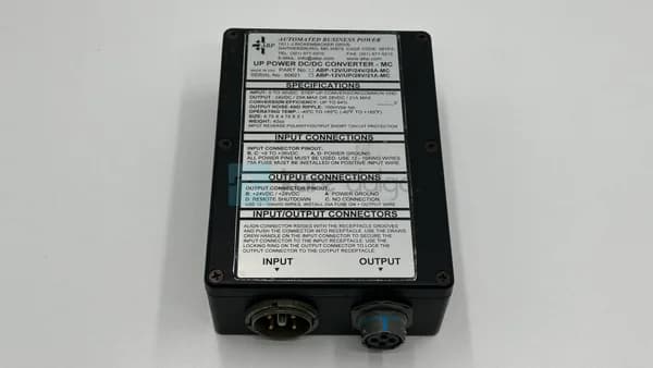
In DC-DC converters, efficiency and heat management are not separate issues, but two sides of the same design equation. The correct approach is to read the efficiency at the actual operating point, calculate the power loss, consider derating and ambient temperature, and establish the thermal path (TIM, baseplate, heatsink, airflow) accordingly. A few percentage points of efficiency gain often significantly reduces the cooling cost and failure risk. To select a power module suitable for your application or compare different efficiency and thermal profiles, you can review the products in the DC-DC Converter category, and request a quote from Kare Dalga for the most suitable module for your operating point. Options like Abp 12V/up/28V/21A-MC and Artesyn NFC25-24T05-12 are a good starting point for different power and isolation requirements.