
What is an EMI Filter? Choosing the Right Filter for EMC Compliance
EMI Filtersare a passive component that suppresses the electromagnetic interference (EMI) emitted or received by an electronic device over its power line. Switch-mode power supplies, motor drives, LED power supplies, and inverters produce sharp-edged currents at MHz levels, so the proper selection of a power line filter not only enables your device to pass EMC certification but also protects sensitive circuits in the environment. In this article, we explain what an EMI filter is, how common mode and differential mode noise are suppressed, how to select it based on current/voltage/leakage current criteria, and common mistakes in practice from an engineering perspective. Our goal is to illustrate how to align the attenuation curve in the datasheet with your actual design.
What is an EMI Filter and How Does It Work?
The EMI filter is essentially a low-pass network: it passes the low-frequency useful power component (50/60 Hz or DC) with almost no loss, while attenuating the noise components in the kHz–MHz band. A typical line filter consists of the following elements:
- Common mode coil (CMC): The phase and neutral windings are wound on the same core in reverse phase. The magnetic fields generated by the useful current cancel each other out, so the core does not saturate; on the other hand, the common mode noise flowing in the same direction in both lines encounters high impedance.
- X capacitors: Connected between phase and neutral, they short-circuit the differential mode noise. Self-healing, X1/X2 class safety capacitors are used as they are exposed to the mains voltage.
- Y capacitors: Connected between the hat and the protective ground (PE), they drain the common mode noise to ground. Their values are directly limited by the leakage current limit.
This combination of elements creates an impedance mismatch in both common and differential mode paths, and reflects the noise back to the source. This is the most practical and widely used method for suppressing emissions propagated via conductivity. An important detail: the insertion loss provided by the filter depends on the source and load impedances. Datasheet curves are typically measured in a 50 Ω/50 Ω system; in your actual application, the grid impedance and the converter input impedance are different, so the attenuation datasheet value may deviate from the field measurement. Therefore, it is always necessary to verify the filter selection with a preliminary compatibility measurement.
Square wave catalog's EMI Filter category includes various topologies, ranging from single-phase chassis-type modules to high-current industrial models.
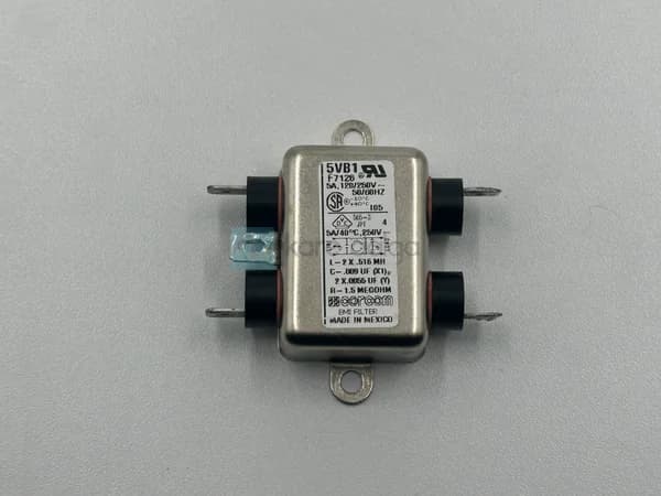
 For compact single-phase applications, the Corcom 5VB1 EMI filter — a typical line filter with IEC inlet and chassis mounting.
What is the difference between EMI and EMC?
The two terms are often confused, but they are different. EMI (Electromagnetic Interference) is a physical phenomenon: the generation of unwanted electromagnetic energy by a circuit, or its susceptibility to such energy. EMC (Electromagnetic Compatibility) is a goal: the ability of a device to both keep its emissions below limits (emission) and operate without degradation in the face of external interference (immunity).
An EMI filter affects only conducted emissions (typically 150 kHz–30 MHz) and partially immunity. For radiated emissions (30 MHz and above), PCB layout, shielding, and enclosure design are also required. So a filter alone cannot guarantee CE/EMC compliance; but it is the most critical component for passing conducted emission testing.
Practical rule: Most conducted emission problems caused by switching frequency and harmonics can be solved with a properly chosen input filter. Radiated problems are usually due to layout and cabling.
What Criteria Should Be Considered in EMI Filter Selection?
Proper EMC filter selection is not just about choosing a filter based on the insertion loss curve in the datasheet. Evaluate the following parameters in order:
1. Nominal voltage and frequency
The filter's nominal voltage should cover the network voltage (e.g., 250 VAC) and frequency. Using a single-phase filter in a three-phase system is a common mistake.
2. Rated current and temperature derating
The rated current of the filter must meet your load current at ambient temperature. Filters are typically derated above 40 °C; it is typical for the rated current to drop by 60–70% at operating temperatures between 55 and 70 °C. In addition to the continuous current, take into account the heating due to copper loss in the coil.
3. Required insertion loss
Perform a pre-compliance measurement, determine by how many dB you exceed the limit, and select the filter to provide the required attenuation in that frequency band. The common mode and differential mode curves are provided separately; distinguishing the mode of the problem in the LISN measurement clarifies the selection.
4. Leakage current
Y capacitors drive leakage current to ground. In medical devices, portable equipment, or personal contact applications, this current is subject to hard limits (e.g., microampere levels in medical applications). Requesting a large Y capacitor for high attenuation may cause you to exceed your leakage current limit; these two criteria often conflict.
5. Topology, leakage path, and mounting
Single-stage filters are low-cost and sufficient for most applications, while heavy-duty power converters may require two-stage filters. Chassis type, DIN rail type, wired (lead) or in-circuit module options are determined by your mechanical constraints.
| Criteria | Low power single phase | Industrial/high current | Module/PCB internal |
|---|---|---|---|
| Typical current range | 1–10 A | 10 A and above | Module-dependent (DC busbar) |
| Mounting | Bus / IEC input | Bus / DIN rail | SMD / through-hole |
| Typical usage | Office device, small SMPS | Driver, inverter, panel | DC-DC module input |
| Sample Product | Corcom 5VB1 | Delta FL75L10-A | Picor QPO-1LZ |
In industrial panels that require higher current Delta Electronics FL75L10-A models are preferred, while in compact systems Delta FL75L05-A is chosen. Kare Dalga products from Delta Electronics are widely used, especially in power-dense applications.
 Industrial power supply lines for Delta FL75L05-A EMI filter.
DC Lines and Power Modules for EMI Filtering
Noise on the DC bus, up to the AC input, is also important. The current ripple and high-frequency noise generated at the input of switching converters affect both the input source and other modules connected to the same bus. At this point, specially designed input filters for module entry, such as the Vicor/Picor family, come into play. Picor filters come into operation.
Picor QPO-1LZ and Picor 9LZ-01 (QPI-9LZ-01) such active/passive input filter modules are used to suppress common mode and differential mode noise at the DC-DC converter input and meet the conducted emission limits in MIL/avionic standards. These modules save both space and design time by integrating a discrete element-based filter into a single package.
 A compact EMI solution for DC-DC module input: Picor QPO-1LZ input filter module.
An additional point to consider when selecting a filter on the DC side is the interaction between the filter input impedance and the converter's negative input impedance. An improperly sized LC input filter can create an unstable control loop together with the converter (Middlebrook criterion). Therefore, a damping element in DC input filters should not be neglected in most cases.
In traditional safety/grid applications, LCR Electronics LCR 091.02001.00 line filters are used; LCR Electronics and Corcom are established options in classic IEC entry and chassis-type modules.
Common Mistakes in Application
- Poor grounding: If the PE connection of the filter is made with a long and thin cable, the effect of the Y capacitors is almost eliminated. The filter body must be connected to the chassis with a low-impedance, wide surface.
- Co-location of input and output cables: If the filtered output cable runs parallel to the unfiltered input cable, the noise is re-coupled capacitively/inductively and the filter is bypassed.
- Incorrect location: The filter should be placed as close as possible to the noise source (converter) and the input point of the cabinet.
- Mode incompatibility: Selecting a filter with a common mode dominant when the problem is in the differential mode (or vice versa) defeats the purpose of the attenuation. Measure first, then select.
- Ignoring derating: Drawing an equal load to the supply current and operating at high ambient temperatures creates excessive heating and saturation in the transformer.
Frequently Asked Questions
Is an EMI filter the same as an EMC filter?
In practice, they are used to identify the same component. "EMI filter" refers to the physical device that suppresses noise, while "EMC filter" emphasizes the purpose of ensuring the EMC compliance of this device. In product catalogs, both refer to the power line filter.
Is a single-stage filter sufficient, or is a two-stage filter required?
In low-power and relatively clean applications, a single-stage filter is often sufficient. However, in high di/dt producing inverters, motor drivers, or densely switched power supplies, and if you are exceeding the limit over a wide bandwidth, a two-stage filter provides higher insertion loss. The decision should be based on the amount of exceedance in your preliminary compliance measurement.
Why does the EMI filter increase the leakage current?
The Y capacitors that drain the common mode noise to ground also drain a small current to ground at the mains frequency. As the Y value increases, both the attenuation and the leakage current increase. Therefore, the limit of the leakage current in medical and portable devices directly restricts the maximum Y capacitance that can be selected.
Where should I place the filter in the device?
The filter should be placed at the point where the AC/DC input enters the enclosure and, if possible, as close as possible to the source of the noise. The input and output conductors should run through separate paths, and the filter body should be grounded to the chassis with a wide contact surface. Incorrect placement can render even the best filter ineffective.
Summary and Next Step
EMI filter selection is an engineering decision that considers voltage and current nominal values, temperature derating, required insertion loss, leakage current limit, and mounting constraints. The best approach is to take a preliminary compliance measurement in your design to determine whether the problem is common mode or differential mode, and then select a topology suitable for this profile. A well-chosen filter shortens your EMC certification process and increases reliability in the field.
from single-phase chassis types to industrial high-current models and DC module input filters for different needs our EMI Filter category you can review; you can request a quote from the Kare Dalga team for a model and stock status suitable for your application. When the correct filter is selected with the right criteria, your noise problem is solved at the design table.