
Power Modules for Railway Applications and EN 50155
Electronic systems used in railway vehicles operate in one of the most demanding working environments in the world: constant vibration, wide temperature ranges, unstable battery line voltages, and electromagnetic noise. The most critical mistake to make when selecting a railway power supply under these conditions is to try to use a commercial or industrial class module directly on the rail. This is where the EN 50155 standard comes into play. In this article, we discuss how to select power modules for railway applications, what EN 50155 means in practice, and the design requirements of railway DC-DC converters from an engineering perspective. By the end of the article, you will have a checklist to select the right components for an on-vehicle power distribution architecture.
What is EN 50155 and why is it so important?
EN 50155 is the European standard for electronic equipment used in railway rolling stock. The standard covers a range of topics, including power supply, temperature resistance, humidity, vibration and shock, EMC, insulation coordination, and lifetime reliability. It is not sufficient for a module to be qualified as “EN 50155 compliant” on the supply side; the standard refers to the entire equipment in which the module is part of. Therefore, a power module’s compliance with the relevant substandards is a critical prerequisite that makes the work of the system integrator much easier.
The standard is based on the supply classes referenced by EN 50155 in terms of power input characteristics. Railway battery line nominal voltage values are typically defined at 24 V, 36 V, 48 V, 72 V, 96 V, and 110 V levels. What the engineer should pay particular attention to is not the nominal value, but the voltage tolerance window of the line: the standard expects the equipment to continue operating despite wide fluctuations in the nominal voltage (for example, approximately 0.7 to 1.25 times the nominal value continuously, and narrower ranges for short durations). In addition, specific scenarios are defined in which the equipment must continue operating for a certain period of time during micro-interruptions and voltage dips.
What parameters are critical in a railway power supply?
When evaluating a power module in a vehicle-mounted application, one should not get stuck on the efficiency value on the first line of the datasheet. The key determinant is the provision of the following parameters in combination:
- Wide input range: Modules with a wide input range that can continuously meet a wide band of the nominal line value, preferably with a 4:1 input ratio, offer a significant advantage in rail applications.
- Galvanic isolation: High isolation voltage is required to break noise and ground loops between the vehicle body and systems with different potentials.
- Wide operating temperature: In outdoor cabinet-mounted applications where convective cooling is limited, the behavior of the derating curve at high temperatures is critical.
- Vibration and shock resistance: Soldered connections, transformer cores, and large electrolytic capacitors are the components most affected by vibration.
- EMC performance: It is expected that conducted and radiated emissions will be limited so as not to interfere with rail signaling bands.
These parameters are provided by industrial-class isolated DC-DC modules, which often form the core of railway applications. Options with a wide input range and high isolation from the square wave catalogue DC-DC converter family fit this profile well. For example Artesyn RFB300-24S12-R5Y, as a high-power module producing 12 V output from a 24 V line, can be considered for on-board distribution applications.
 High-power isolated DC-DC modules form the core of on-board power distribution in railways. Explore: Artesyn RFB300-24S12-R5Y
How is the railway DC-DC architecture designed?
In railway vehicles, power distribution is typically resolved with a two-stage architecture. The first stage is a high-power, isolated pre-regulator that converts the noisy and widely tolerant voltage of the vehicle battery line (e.g., 24 V or 110 V) into an intermediate bus voltage. The second stage consists of smaller converters that produce the point-of-load voltages (PoL — Point of Load) required by the digital and analog loads on the board from this clean intermediate bus.
This approach has two major advantages. Firstly, the first stage takes on the heavy load of isolation and wide input tolerance, allowing the second-stage modules to be smaller, more efficient, and less expensive. Secondly, sensitive loads are not affected by voltage drops on the line thanks to the hold-up capacity on the intermediate bus. For the first stage, BEL Power Solutions 0RSB-50R080 like high-power brick-type modules; for the second stage, Astec ASA00BB18-L and Astec ASA00CC18-L like compact solutions are typical starting points.
 In the two-stage power architecture, the first stage assumes isolation and wide input tolerance.
Hold-up time and micro-interruptions
One of the most overlooked requirements of EN 50155 is the behavior during power interruptions. The standard expects the equipment to operate without interruption for 10 ms in case of certain interruption classes or to recover without reboot. This requires either sufficient capacitance on the input side of the module or a hold-up capacitor designed on the intermediate rail. The engineer can roughly size the required energy E = ½·C·(Vinitial² − Vmin²) with the relationship; where Vmin is the minimum input voltage at which the second-stage modules can still regulate.
Why is thermal management and vibration different on the railway?
The performance measured in the laboratory of a power module is often very different from the actual operating temperature experienced on the rail. Enclosures in railway vehicles are typically designed to be leakproof due to dust, water, and EMC considerations, which often makes forced air cooling impractical. As a result, the module is forced to dissipate the heat it generates only through conduction and natural convection. Therefore, it is not a single performance figure in the datasheet that is the determining factor, but rather the derating curve drawn according to ambient temperature: how long the module can sustain its specified full power at a given temperature and how rapidly its power must be reduced above that temperature. These are among the most critical inputs for the engineer's design.
The engineer must design a thermal path that will keep the module's housing or baseplate temperature within a safe range of the target ambient temperature. This may include the use of thermal grease to attach the module to a heatsink or vehicle chassis, and the selection of a thermal interface material (TIM) if necessary. Baseplate-type modules offer a distinct advantage over open-frame modules in enclosed enclosures, as they can dissipate heat through their bodies.
Vibration, however, requires a separate design discipline. The railway profile includes continuous random vibration and shock pulses over a wide frequency band. The most stressed components are large transformer and coil cores, high-profile electrolytic capacitors, and heavy connectors. Therefore, in modules designed for railway applications, critical components are often mechanically supported with potting/conformal coating and a low-profile, surface-mount dominated layout is preferred on the board. During the procurement phase, the mechanical lifetime expectation of a module, not just its electrical one, must be taken into account.
Power Module Comparison for Railway Applications
The following table summarizes common module types and evaluation criteria for railway projects. The values are principle categories and the technical documentation of the relevant product should be consulted for a definitive selection.
| Criteria | High-power isolated front regulator | Compact PoL/2nd-stage module |
|---|---|---|
| Typical location | Battery line input | Ara busbar → board-top load |
| Insulation requirement | High (mandatory) | Mostly uninsulated sufficient |
| Input range | Wide (e.g. 4:1) | Narrow, clean ara busbar |
| Power level | High (hundreds of W) | Low–medium |
| Cooling strategy | Cooler/heatsink housing | PCB copper area |
Low-power, isolated point supplies Abp 12V/UP/28V/21A-MC and similar modules can also be used to create auxiliary rails in the design.
Beyond the power module: vehicle-mounted equipment compatibility
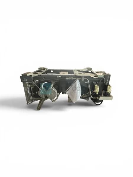
In railway projects, power electronics does not only power electronic boards; pneumatic and mechatronic systems are also connected to this power infrastructure. For example, the control and auxiliary circuits of air production units that power brake and door systems are also subject to the same on-board standards. As part of this ecosystem, Kare Dalga, Knorr Bremse branded VV120T air compressor (5018270004) also includes railway on-board equipment in its catalog. Providing power modules and mechanical parts from a single supply point in a maintenance or refurbishment project significantly reduces the risk of component incompatibility and supply time.
When evaluating the brand, it makes sense to examine the strong suppliers in the railway portfolio. Our catalog includes modules from power electronics brands such as Artesyn, Astec, BEL Power Solutions and Abp. You can view all options from a single point by checking the Railway category.
Frequently Asked Questions
What is the difference between EN 50155 and EN 50121?
EN 50155 is the umbrella standard covering the general working conditions (power, temperature, vibration, reliability) of electronic equipment on railway vehicles. The EN 50121 family specifically defines the electromagnetic compatibility (EMC) for railway applications. In practice, a power module must comply with the relevant clauses of both standards.
Can an industrial DC-DC module be used in a railway application?
Direct use is not recommended. Although industrial modules offer wide input and isolation, they do not always meet the vibration/shock resistance, voltage drop hold-up time, and temperature derating profiles expected by the railway. The module's compliance with the relevant clauses must be validated before selection.
Why is a 4:1 input range preferred for railway DC-DC modules?
Railway battery lines fluctuate within a wide tolerance window and experience micro-interruptions. A 4:1 input ratio allows the module to maintain regulation at both nominal and extreme low/high voltages, reducing the risk of restart and interruption.
Why is a two-stage power architecture preferred?
The first stage handles heavy requirements such as isolation and wide input tolerance; the second-stage modules can be smaller, more efficient, and cost-effective. Additionally, the hold-up capacity of the intermediate bus protects sensitive loads from interruptions during voltage drops.
Summary and next step
Selecting a power module for railway applications is much more than the efficiency figure on the datasheet: wide input tolerance, high galvanic isolation, vibration/shock resistance, temperature derating behavior, and hold-up time during voltage drops must be considered together. EN 50155 and related EMC standards frame these requirements in one framework. Handing over the heavy load to a heavily isolated pre-regulator with a two-stage architecture increases both reliability and efficiency. If you want to select a DC-DC converter and other board-level components suitable for your project, or find an equivalent module for an existing board, Railway products in our category and get a quote from our technical team. Let's clarify the correct component list together.