
Isolated and Non-Isolated DC-DC Converter Difference: Which to Choose?
When designing a power distribution architecture, one of the first and most critical decisions is whether to choose an isolated or non-isolated DC-DC converter. This preference directly determines not only the efficiency of the circuit, but also its safety, noise behavior, EMC compliance, and cost. Although isolated and non-isolated topologies may seem like alternatives to each other, they actually exist to solve different problems. In this article, we examine the working logic of both approaches, what the isolation barrier is used for, which one is the correct choice for which application, and the technical criteria that are overlooked in the selection process from an engineering perspective.
If you would like to compare products directly, please visit DC-DC Converter in the category You can start by examining isolated and non-isolated modules; however, understanding the fundamental difference between them before selecting the right product saves time and error cost in the field.
What is an Isolated DC-DC Converter?
An isolated DC-DC converter with a separation of galvanic barrier is a transformer. This barrier is usually provided by a high-frequency transformer: energy is transferred through a magnetic field, with no direct conductive path between the two sides. As a result, the ground reference at the input and the ground reference at the output are electrically isolated from each other.
The practical implication of this isolation is that a fault on the primary side, such as a high voltage spike or ground loop, cannot pass to the secondary side beyond the isolation barrier. The isolation value is typically specified at levels such as 1000 VDC, 1500 VDC, 3000 VAC, and is chosen according to the safety standard of the application. In medical, railway, industrial automation, and communication infrastructure, isolation is often not a preference, but a necessity.
Isolated modules also provide the ability to invert the output polarity, generate multiple independent outputs, and establish flexible grounding schemes between input and output. High-power brick-format modules like the Artesyn RFB300-24S12-R5Y in our catalog are typical examples of this isolated architecture.
 Isolated DC-DC converter example: input and output sides are separated by a galvanic barrier. Artesyn RFB300-24S12-R5Y
How Does a Non-Isolated DC-DC Converter Work?
In non-isolated converters, the input and output share a common ground reference. This class includes switching topologies such as buck, boost, buck-boost, and SEPIC. Energy transfer occurs through an inductor instead of a transformer; this means fewer components, a smaller volume, and usually higher efficiency.
Since there is no isolation barrier, these modules are physically more compact and more cost-effective. They are ideal for converting voltage levels between blocks sharing the same ground plane, for example, to produce 3.3 V core voltage from a 12 V line. Point-of-Load (PoL) regulators are mostly un-isolated designs.
However, since there is no primary-secondary separation in un-isolated designs, noise and transient overvoltages on the input side can reach the load directly. Therefore, more care should be taken with input filtering and layout discipline when selecting un-isolated modules.
Isolated topologies also have significant differences within themselves. A buck converter can only produce an output voltage lower than the input voltage, while a boost converter raises the output above the input. In cases where the input voltage wanders both below and above the output (for example, a battery discharging over a wide range), buck-boost or SEPIC topologies come into play. Ensuring this behavior matches the input voltage profile in your application when selecting a module prevents unexpected regulation losses. Modules like the Artesyn NFC25-24T05-12 in our catalog are examples of options that can be considered for board-level conversions with multiple output requirements.
What are the Basic Differences Between Isolated and Non-Isolated Converters?
If we were to sum up the difference between the two topologies in a single sentence: Isolated modules provide security and noise separation, while non-isolated modules offer efficiency, space, and cost advantages. The table below summarizes the key criteria to consider when making a selection.
| Criteria | Isolated DC-DC | Unisolated DC-DC |
|---|---|---|
| Input-output ground | Separate by galvanic | Common reference |
| Energy transfer | High-frequency transformer | Inductor (coil) |
| Typical efficiency | Usually lower (barrier losses) | Usually higher |
| Volume/Cost | Larger/Higher | Smaller/Lower |
| Security/standard compliance | Soil cycle and shock protection | Limited (common soil) |
| Polarity / multiple outputs | Flexible (negative, multiple outputs possible) | Usually single polarity |
| Typical use | Industry, rail, medical, communications | PoL, on-board voltage conversion |
A point not reflected in the table but important in practice is EMC behavior. In isolated modules, common-mode noise can occur through transformer winding capacity; therefore, it is necessary to add appropriate filtering to the input and output in designs that require high isolation. In non-isolated modules, differential mode noise is prominent. In both cases, the board layout affects noise performance in a decisive manner, regardless of the topology.
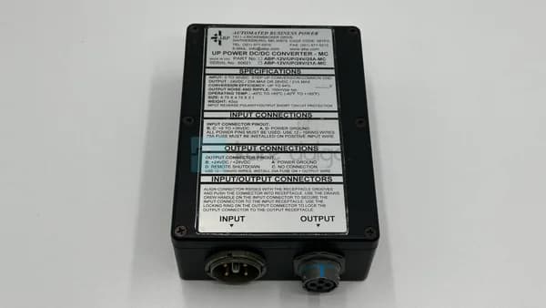
 High current industrial DC-DC module. ABP 12V/up/28V/21A-MC
Which Application Should Be Selected?
The choice is made not with the question "which is better," but with the question "what does the application require?" The following approaches are useful in the field experience:
- If safety or standards are mandatory, select isolation. If there is a risk of human contact (medical device), a high-voltage environment, or an EN/IEC safety requirement, galvanic isolation is not open to discussion.
- If there is a soil loop problem, select isolated. When connecting subsystems with different soil potentials (e.g., sensor to controller), isolation cuts off measurement noise and leakage currents.
- Select unisolated for on-board voltage conversion. In step-down conversions such as 24 V → 12 V → 5 V → 3.3 V between blocks sharing the same ground, unisolated buck regulators provide efficiency and space savings.
- If efficiency and volume are critical, select unisolated. If battery life or thermal budget is critical, the additional loss and volume introduced by the isolation barrier may not be desirable.
Hybrid architectures are common: a single isolated "pre-regulator" at the system input creates a safe and noise-free intermediate bus, then multiple non-isolated PoL regulators on the card are fed from this bus. This approach optimizes both safety and efficiency. Astec ASA00BB18-L and Astec ASA00CC18-L modules are often found in such distributed power architectures.
 Module used in distributed power architecture. Astec ASA00BB18-L
Overlooked Technical Criteria in Selection
After the isolation decision is made and the module is narrowed down, the following parameters are often neglected, although they determine circuit stability:
- Input voltage range: In an industrial environment where busbar voltage is fluctuating, a wide input range of 2:1 or 4:1 ensures the module's stable operation.
- Isolation voltage and resistance: The "Isolated" label alone is not sufficient; the barrier's VDC/VAC rating and whether it is continuous or test voltage must be checked.
- Load and ripple regulation: The amount of deviation the output voltage shows under load variation is a determinant for precise loads.
- Operating temperature and derating: The module's rated power is mostly valid at a specific ambient temperature; it is necessary to evaluate the power derating curve at high temperatures.
- Idle current/ efficiency curve: Efficiency is not a single point; examining the efficiency curve in your actual load profile ensures proper thermal design.
These criteria apply to both isolated and non-isolated modules. When examining the product families of brands Artesyn, Astec, ABP and BEL Power Solutions, you will see that manufacturers offer products in different isolation classes; it is a good practice to compare several alternatives in the same power class to capture the most suitable value for your design.
Another critical point is reliability and lifetime calculation. In isolated modules, the number of components increases due to the transformer and additional components; this is a factor to be considered in the MTBF (mean time between failures) calculation. In contrast, a properly sized isolated module can increase overall system reliability by eliminating field failures caused by noise and ground loops. In industrial applications with high current requirements ABP 12V/up/28V/21A-MC modules, evaluating the thermal derating curve and mounting surface cooling requirements at an early stage prevents overheating problems that may occur in the field.
Frequently Asked Questions
Are non-isolated DC-DC converters not safe?
Non-isolated modules are not inherently unsafe; they are extremely safe when used in the right place. "Safety" here refers to applications that require galvanic isolation (human contact, high voltage, ground loop). In intra-card conversions where shared ground does not create a problem, the non-isolated module is the correct and safe choice.
Is the isolated converter always more efficient?
No, usually the opposite is true. Isolated modules often have slightly lower efficiency compared to equivalent non-isolated modules, because the isolation barrier (transformer) introduces additional loss. The reason to choose an isolated module is not efficiency, but safety and noise isolation.
Can I use isolated and non-isolated converters together in the same system?
Yes, this is a very common design. At the system input, a separate pre-regulator is used to create a secure busbar, and on the card, a large number of unisolated PoL regulators are used, powered from this busbar. This optimizes both safety and efficiency and cost.
What value should I choose for the isolation voltage?
The isolation voltage is determined by the safety standard and operating voltage of your application. As a general rule, a barrier withstand voltage well above the continuous operating voltage should be selected. Even if there is no standard requirement, an insulation class above the rated value should be chosen to leave a margin against transient overvoltages.
Summary and Choosing the Right Module
The choice of isolated and non-isolated DC-DC converters is an engineering decision based on the requirements of the application, rather than what is "better". If safety, standard compliance, or ground loop issues are a concern, isolation is preferred; if efficiency, size, and cost are prioritized and common ground does not create issues, non-isolated topology comes to the forefront. In many modern systems, the most sensible solution is a hybrid architecture that combines isolated pre-regulation with non-isolated PoL regulation.
To compare isolated and non-isolated modules suitable for your design from a single point, you can review our DC-DC Converter category; you can evaluate alternatives based on input range, isolation value, and power class. It is sufficient to contact the Kare Dalga team to determine the most suitable module for your application and receive a quote.