
Vicor DC-DC Converter Family: Modules and Applications
For an engineer designing power conversion systems Vicor DC-DC converter series represents a very different engineering philosophy from traditional open-frame power-over-Ethernet solutions: high switching frequency, aggressive optimization in terms of power density, and a modular "building block" approach. In this article, we will discuss the main families of Vicor power modules, their operating topologies, which module makes sense for which application, and how a Vicor converter. Our goal is not to sell, but to provide you with a solid reference framework to make the right decision. You can review the current modules in our inventory under the DC-DC Converter category can be reviewed below.
What is a Vicor DC-DC Converter and why is it different?
Vicor is a manufacturer that offers power conversion in fully integrated, sealed (encapsulated) modules, rather than in discrete designs. While a conventional top-mounted converter typically switches in the 100-300 kHz range, some of Vicor's topologies extend to the MHz level. Higher frequency means smaller magnetic components and filter capacitors, which significantly increases the module's wattage per cubic inch (W/in³) value.
The second distinguishing feature is the modular architecture. Instead of treating a power bus as a single block, Vicor breaks it down into functional components: front-end AC-DC or bus processing, intermediate bus conversion, and point-of-load regulation. The engineer assembles these components as needed to create a custom power chain. This approach provides a repeatable and validated design foundation, especially for long-life projects such as defense, aerospace, and industrial infrastructure.
Thirdly, many Vicor modules use quasi-resonant or zero-current/zero-voltage switching (ZCS/ZVS) types of soft switching topologies. This improves both efficiency and thermal behavior by reducing switching losses and thus EMI generation. From an engineer's perspective, the practical implication is that you can achieve the same output power from a smaller enclosure, with less cooling effort, and often with a cleaner noise spectrum. However, the high switching frequency still requires more careful design of the input/output filter and grounding arrangement in the board layout; it is important to adhere to the recommended application scheme in the datasheet to achieve the module's performance in the field.
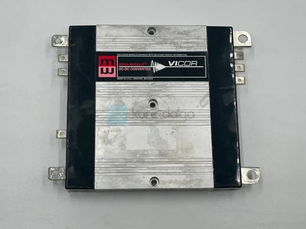
 A module from the Vicor Mega Module family; integrated, sealed body structure. Check out the VI-M0L-IV module.
Vicor Power Module Families and Topologies
The Vicor portfolio, although seemingly complex at first glance, actually revolves around a few basic architectures. Below, we summarize the most common families from a practical perspective.
Maxi / Mini / Micro and VI-2xx Series
This classic family is a scalable body system for a wide input voltage range and different power classes. The "Maxi" is the highest power, the "Micro" is the most compact version; however, they all share the same control and pin layout philosophy. The Vicor MI-221-IW module is a typical example of the industry/military class construction unique to this family, and represents variants designed for extended operating conditions.
Mega Module and Integrated Solutions
The Mega Module approach saves board space and assembly labor by combining multiple functions (e.g., filter + converter) into a single package. Mega Module VI-M0L-IV is an example of this philosophy; it reduces the validation burden on the system integrator for separate components.
VI Chip and Factorized Power: BCM / PRM / VTM
Vicor's more modern approach is known as the "Factorized Power Architecture" (FPA). Here, voltage conversion (transformation) and regulation are separated: the PRM provides regulation, while the VTM provides fixed-ratio, fast-response voltage conversion. The BCM, as a fixed-ratio data path converter, provides high efficiency isolation and scaling. This architecture is preferred for low-loss conversion near the load point, especially in 48V data path architectures (which are becoming increasingly common in modern server and telecom applications).
A significant advantage of this separation is that regulatory losses are concentrated at a controllable point, rather than being spread throughout the system. Fixed-ratio converters, such as VTM, behave like transformers, raising current with very high efficiency; this allows high-current, low-voltage loads (such as processor cores) to be fed very close to the load point, minimizing distribution losses. For designers who prefer a more classical architecture, the VI-2xx and Mega Module families continue to offer a fully regulated and isolated solution in a single module. Which path you choose depends largely on the size of your system power budget and the nature of your distribution architecture (centralized or distributed).
 24V input, 12V output compact Vicor module, the V24A12C400BN is suitable for a typical industrial data path application.
How to Choose a Vicor Module?
Selecting the right module requires more than just looking at a single watt value on the datasheet. The following sequence is a practical decision flow that works in the field:
- Input voltage range: Select a module that covers the nominal value as well as transient and low/high fault conditions. In military and railway applications, a wide range ("W" or "I" class variants) is critical.
- Isolation requirement: Does the input and output require galvanic isolation? Isolated modules address safety and ground loop issues; non-isolated point regulators can offer higher efficiency.
- Power output and current: Take into account the peak load profile, not just the continuous value.
- Thermal solution: The baseplate temperature of the module, cooling method (conduction, airflow), and derating curve directly determine the design life.
- Mechanical and environmental class: Vibration, shock, humidity, and temperature range (e.g., -40 °C…+100 °C base temperature) must be suitable for your application.
Examples by Input/Output Configuration
Different input/output combinations within the same chassis make it easier to accommodate different rails without redesigning your system architecture. The table below summarizes the typical configuration practices of some of the Vicor modules in our catalog. (For exact electrical values, always refer to the technical documentation for the specific product.)
| Module | Typical Input | Typical Output | Featured Usage |
|---|---|---|---|
| V24A12C400BN | 24V nominal voltage | 12V | Industrial data path / interface conversion |
| V24A28C400BN | 24V nominal voltage | 28V | 28V for avionic/vehicle systems requiring voltage |
| V24C12T100B3 | 24V nominal | 12V | Compact budget-powered board-level applications |
| V24C5T100B3 | 24V nominal voltage | 5V | Logic/sensor power supply point |
| MI-221-IW | Wide bandwidth (Class I/W) | Modular design | Rugged military/industrial environment |
 Logic and sensor power supply with 5V output V24C5T100B3 module.
Application Areas of Vicor Modules
The power density and modularity of Vicor modules make them particularly valuable in certain industries:
- Defense and aerospace: Wide input range, MIL-compliant variants, and high reliability in systems where safety is critical. 28V output variants are compatible with avionics rails.
- Rail and transportation: Power systems in vehicles that require wide input, high vibration and temperature tolerance.
- Industrial automation and test equipment: Clean, low-noise power in places where a compact power budget is required.
- Telecom and data centers: 48V data path architectures, BCM/VTM-based load point conversion.
- Medical and measurement devices: Precision electronics where isolation and low EMI requirements are paramount.
These modules typically perform best when used with an EMI/filter layer and appropriate input protection. You can compare the full range of Vicor products on the Vicor brand page and alternative power solutions under the DC-DC Converter category you can compare below
Thermal Management and Reliability: Bringing the Module to Life in the Field
Reaching the peak power in a Vicor module's datasheet and delivering that power reliably for years are two different things. The bridge between them is thermal management. The main losses on the module are the sum of switching and transmission losses; these losses are converted to heat and must be dissipated through the baseplate.
There are a few practical points to consider in the design:
- Take the derating curve seriously: The power-temperature derating curve provided by the manufacturer shows that the maximum power a module can deliver above a certain baseplate temperature decreases. Design your system according to the worst-case corner of the curve, not the nominal point.
- Thermal interface material (TIM): The thermal resistance between the module and the heatsink should be minimized with the correct TIM and appropriate mounting torque. Unequal pressing forces create local hot spots.
- Cooling strategy: Determine early on which of the options for conduction (cold plate), forced air, or natural convection is appropriate; this also affects the choice of chassis family.
- Cycle life: Thermal cycling creates fatigue on solder joints and connection points. In rail and avionics applications operating over a wide temperature range, this factor directly determines life.
In insulated modules, there is also a insulation suitable for operating voltage and creepage/clearance distances is critical for both security and reliability. The V24A28C400BN, these requirements are often subject to stricter standards. With proper thermal and mechanical design, a Vicor module can operate for decades without requiring maintenance, making it attractive for hard-to-reach or critical infrastructure applications.
Frequently Asked Questions
Are Vicor DC-DC converters isolated?
The Vicor portfolio includes both isolated and non-isolated modules. Isolated modules provide galvanic separation between input and output, solving safety and ground loop issues. To determine your needs, you should look at your system grounding architecture and safety standards.
What is the most critical parameter when selecting a Vicor module?
There is no single parameter; however, the input voltage range, isolation requirement, and thermal solution (baseplate temperature and derating) are typically the determining trio. These three criteria directly affect whether the module will operate reliably and have a long lifespan in your application.
What is the difference between the V24A12C400BN and the V24C12T100B3?
Both modules provide 24V input and 12V output, but the body families, power classes, and mechanical structures are different. While the V24A series typically represents a different power/package class, the V24C series is more suited to compact top-mount applications. To make an informed decision, evaluate your power budget and installation space.
Are the old Vicor modules still available?
Many industrial, military, and rail applications require long product lifetimes, and Vicor modules that are no longer in production or difficult to obtain may be needed. We respond to maintenance and replacement needs by including these types of modules in our catalog as square wave products; you can query for the part you are looking for.
Summary and Next Step
The Vicor DC-DC converter family provides reliable power conversion across a wide range, from defense to railway, and from test equipment to telecom, thanks to its high power density, modular architecture, and wide operating conditions. The key to selecting the right module is to evaluate the input range, isolation, and thermal management together. If you are not sure which Vicor power module is suitable for your project, review the Vicor modules in our catalog or get a quote from our DC-DC Converter category; when you share your technical requirements, we will determine the most suitable configuration together.