
Insulation Tester (Megohmmeter) User Guide
The most subtle warning an electrical machine, cable, or panel gives before failing is the gradual deterioration starting in the insulation material. The most reliable way to see this deterioration before leakage, arcing, or fire occurs insulation testing device, i.e., insulation resistance measurement using a megohmmeter. In this guide, we examine how the megohmmeter works, how to choose the correct test voltage, how to interpret ratios such as PI and DAR, and the steps to follow for safe measurement in the field from an engineering perspective.
Our goal is not to sell you something, but to ensure you interpret the measurement correctly. Nevertheless, while looking for a device for your laboratory or field, you can take a look at the insulation testing devices in the Kare Dalga catalog. insulation testing device products.
What is an insulation testing device (megohmmeter) and how does it work?
A megohmmeter is a device that applies a high DC test voltage (typically between 50 V and 5,000 V) to the insulation material between two conductive points, measures the very small leakage current passing through this material, and gives the result as resistance via Ohm's Law. The result is usually in the order of megaohms (MΩ), gigaohms (GΩ), or even teraohms (TΩ); that's why the device is called a 'megohmmeter'. The few volts of measurement voltage of a regular multimeter cannot distinguish resistances at this level, so a separate device is required for insulation measurement.
When a DC voltage is applied, it creates a current consisting of three components: surface leakage current, geometric capacitive charge current, and time-absorbed polarization (absorption) current. In a solid insulator, the total current initially starts high and decreases to a very small leakage current within minutes; therefore, the measured resistance value increases over time. In a humid, dirty, or aged insulator, the current remains high and the resistance decreases. The sensitivity of the megohmmeter comes from its ability to read this time-dependent behavior.
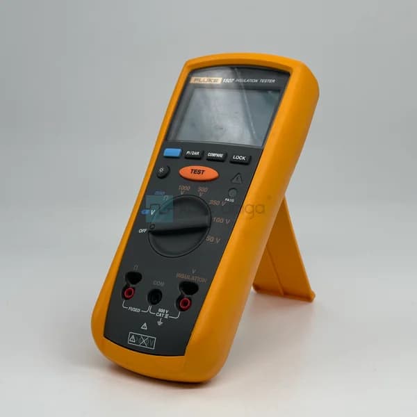
 An example of a megohmmeter that offers multiple test voltage options: Fluke 1507 Insulation Resistance Tester.
How to select the correct test voltage?
The most critical decision in selecting and using a megohmmeter is the applied DC test voltage. The general rule is that the test voltage should be higher than the operating voltage of the device, but not so high as to stress the insulation. If you select a low test voltage, you will miss the initial weakening of the insulation, and if you select a voltage that is too high, you may damage an already fatigued insulator.
The following table summarizes the commonly used test voltage levels for field operating voltages. These are general practical values; always refer to the value recommended by the equipment manufacturer and applicable standards (e.g., IEC 60364-6).
| Circuit/equipment operating voltage | Common test voltage | Typical application |
|---|---|---|
| Rating up to 50 V (SELV/PELV) | 250 V DC | Low-voltage signal and control circuits |
| 50 V – 500 V | 500 V DC | Power plant, small motors |
| 500 V – 1000 V | 1000 V DC | Industrial panel, driver, cable |
| 1 kV and above | 2500 V – 5000 V DC | OG motors, transformer, OG cable |
If you are working in a wide range of voltages, a device that offers multiple steps is more flexible in the long term than a single fixed voltage. Evaluating complementary measuring instruments such as multi-step megohmmeters and multimeters together at this point expands your field of measurement.
PI and DAR ratios: correctly interpreting insulation resistance
A single MΩ value at a given moment can be misleading, as it is highly influenced by temperature and humidity. In professional diagnostics, two-time-based ratios are used, and the beauty of these ratios is that they are independent of the absolute value:
- DAR (Dielectric Absorption Ratio): The ratio of resistance at 60 seconds to resistance at 30 seconds. In practice, 1.25 and above are generally considered good; 1.0 or below is suspect.
- PI (Polarization Index): The ratio of resistance at 10 minutes to resistance at 1 minute. According to common opinion, 2.0 and above indicate healthy insulation, while 1.0 – 2.0 requires careful monitoring.
The logic is that resistance in solid and dry insulation increases significantly over time, so the ratio is high. In wet or dirty insulation, resistance remains almost constant, so the ratio approaches 1. Therefore, the PI/DAR measurement is a much more reliable predictive maintenance indicator than making a decision based on an absolute value. Modern megohmmeters usually perform this calculation automatically; your job is to record the result as a trend and monitor the decline over time.
Type: The absolute MΩ value is always temperature-dependent. To obtain comparable data, adjust the measurements to a standard reference temperature (usually 20 °C or 40 °C); otherwise, you may see a false deterioration when you measure the same motor in different seasons.
Step-by-step method for safe and accurate field measurements
Insulation testing requires discipline to protect both the equipment and the operator, since it produces high DC voltage. The following sequence applies to most panel, motor, and cable measurements:
- Isolate and lock the circuit: Disconnect the equipment to be tested from power, apply LOTO (lockout/tagout), and verify that it is truly grounded with a multimeter.
- Discharge the capacitive load: Cables and windings remain loaded after testing; discharge them with grounding before and after measurement.
- Remove sensitive components: High DC voltage can damage components such as varistors, fuses, electronic cards; remove them from the circuit before testing.
- Connect the terminals correctly: Connect the megohmmeter's suitable terminals between the conductor and ground/chassis. Advanced users who want to separate surface leakage from the measurement use the guard terminal.
- Apply the test voltage and wait for the period: Wait for 1 minute to read the instantaneous value, 10 minutes for PI; if the device automatically manages the period, monitor the screen.
- Record and discharge: Note the result along with temperature information, then safely discharge and ground the equipment.
Most of these steps require a high-quality handheld multimeter for pre-measurement voltage verification and continuity control. Reliable options to carry in the field include Fluke 115 True RMS Digital Multimeteras a compact alternative Fluke 15B Digital Multimeter and for heavy industrial environments Fluke 77 IV Digital Multimeter are available.
 An ideal handheld multimeter for verifying voltage-free conditions before insulation testing: Fluke 115 True RMS.
What is the difference between a megohmmeter and a multimeter?
They are often confused but solve different problems. A multimetermeasures voltage, current, continuity, and low-to-medium level resistance with low measurement voltage; it is indispensable for diagnosis and verification in live circuits. A megohmmeter applies high DC voltage to measure only insulation resistance, i.e., very high resistances, and is used on de-energized equipment. In practice, they complement each other: first, you verify the circuit is voltage-free with a multimeter, then you test the insulation with a megohmmeter.
While some high-end multimeters offer expanded resistance and improved recording features, they do not replace a true high-voltage insulation test. However, for high-resolution general measurement Agilent U1272A True RMS Digital Multimeter such devices are a powerful complement in the field. The standout Fluke products are a widely recognized reference in the industry for measurement reliability and safety category (CAT) ratings.
A practical setup can be summarized as follows: in process plants and calibration work, a process multimeter (e.g., Fluke 787 Digital Multimeter) that can both measure and power the 4-20 mA loop performs general voltage/continuity verification, then you proceed to insulation testing with a megohmmeter on de-energized equipment. Thus, you complete both live circuit diagnosis and insulation health checks in a single maintenance visit. What's important is that both devices have the appropriate CAT rating and are suitable for the voltage level of your environment.
 A practical complement for process measurement and loop control: Fluke 787 Digital Multimeter.
Frequently Asked Questions
What should be the value of good insulation resistance?
There is no single threshold; the value depends on the type of equipment, voltage class, and temperature. A common rule of thumb is a minimum of 1 MΩ for low-voltage equipment, but hundreds of MΩ or GΩ are often expected for motors and cables. For a more reliable decision, look at the PI/DAR ratios and trends over time rather than the absolute value.
Can I perform the insulation test on a live (energized) circuit?
No. The megohmmeter applies high DC voltage and is only used on equipment that has been de-energized, locked out, and discharged. Testing on an energized circuit can damage the device and pose serious safety risks. Always verify the voltage-free condition with a separate multimeter before making the measurement.
How do I select the test voltage relative to the equipment voltage?
The general approach is to select a test voltage that is one level higher than the equipment operating voltage: 500 V DC for circuits up to 500 V, 1000 V DC for circuits up to 1 kV, and 2500–5000 V DC for medium-voltage equipment. Always refer to the manufacturer's instructions and the relevant standard for the exact value.
Why is PI and DAR measurement more reliable than a single MΩ value?
Because PI and DAR are ratio-based and are largely independent of absolute magnitude and temperature. In good insulation, resistance increases over time, the ratio grows; in wet or damaged insulation, resistance remains constant, the ratio approaches 1. This reduces the risk of error at a single point and provides a meaningful trend for predictive maintenance.
Summary and next steps
The insulation testing device is one of the most effective ways to detect electrical faults before they occur. To get the correct result, remember three things: choose the test voltage suitable for the equipment, interpret the PI/DAR ratios and trend over time instead of absolute MΩ, and perform each measurement with voltage-free verification in a safe LOTO discipline. The megohmmeter and multimeter work as complements to each other, not as substitutes.
When determining the right device for your site or laboratory, you can check out Kare Dalga's insulation test device and multimeter categories, and get a price and stock quote for the model suitable for your application. Let us know the voltage class of your application and the type of equipment you will be measuring, and we can determine the most suitable solution together.