
RF Power Amplifiers: Classes of Operation and Applications
In the final stage of an RF chain, the component that raises a weak modulation signal to a level that can be transmitted to an antenna with power in the hundreds of watts is the RF power amplifier. These amplifiers, which are found everywhere from FM broadcast transmitters to cellular base stations and from radar transmitters to industrial heating systems, have a direct impact on the efficiency, linearity, and thermal reliability of the system, making their proper selection crucial. In this article, we examine the operating classes (A, AB, B, C, and switching classes D/E/F) of RF power amplifiers, critical performance parameters, and application-based selection logic from an engineering perspective. The goal is to provide the correct answer to the question "which amplifier class, which transistor topology, and which module" in your next design.
What is an RF Power Amplifier and Where is it Used?
The RF power amplifier, an active circuit that boosts an input signal in the radio frequency band (typically a few MHz to several GHz) to a power level sufficient to drive a load (usually 50 Ω antenna or transmission line). The key difference from small signal amplifiers is that the output power and efficiency are the primary concerns; here the issue is no longer just gain, but watts per heat, linearity, and ruggedness.
Typical applications include:
- Broadcasting: Final stage drivers in FM/TV transmitters, with hundreds of watts.
- Mobile communications: Base station PA modules, small cell drivers.
- Radar and defense: Pulsed high peak power transmitter stages.
- Industrial ISM applications: Plasma generators, RF heating, MRI gradient/RF drivers.
In the Square Wave catalog, complete applications for all of these RF amplifiers modules and their fundamental building blocks, discrete RF transistors are available together; because in practice, amplifier selection and active component selection are two inseparable decisions.
 A high-power RF amplifier example used in FM broadcast transmitters: Blf278 FM 500 W Amplifier.
What are the Operating Classes of RF Power Amplifiers?
The "class" of the amplifier defines how long the active element remains in conduction (conduction angle) during an RF cycle, and thus the balance between efficiency and linearity. This is the most fundamental engineering choice in RF power amplifier design.
Class A
The active element is on throughout the entire cycle (360° conduction angle). It has the highest linearity and the lowest harmonic generation, making it preferred for sensitive, low-distortion driver stages and measurement amplifiers. The price paid is low efficiency: the theoretical maximum efficiency is approximately 50%, but in practice it is usually much lower. Heat management is critical because it draws constant current.
Class B and AB
In class B, the conduction angle is 180°; the device conducts for half of the cycle. It produces high distortion on its own, but practical linearity is achieved by combining two devices in a push-pull configuration, and theoretical efficiency rises to ~78.5%. Class AB on the other hand, offers reasonable efficiency while suppressing "crossover" distortion by selecting a bias point between A and B. Class AB is the most commonly used class today for communication and broadcast power amplifiers because it balances linearity and efficiency.
Class C
has a conduction angle of less than 180°; the device conducts for only a portion of the cycle. Efficiency is very high (over 80% is possible), but linearity is low. Therefore, class C is ideal for constant-envelope signals: FM broadcast, CW radio, and frequency multipliers are typical examples. It cannot be used directly for modulation that carries amplitude information (e.g., QAM).
Switched-Mode Classes (D, E, F)
In these classes, the transistor operates not as a linear amplifier, but as a switch (fully on or fully off). Under ideal conditions, the element has either voltage or current at any given time, not both, so dissipation theoretically approaches zero, and efficiency approaches 100%. In practice, efficiencies of 85-95% are attained. In exchange, the circuit is extremely sensitive to output matching network and switching speed, and is naturally nonlinear; they are used in modern communication systems that require linearity, along with Doherty architecture, envelope tracking, or digital predistortion (DPD).
 The design of fixed impedance, internally matched integrated amplifier modules simplifies: Bgy33 RF Amplifier.
Class Comparison: Efficiency, Linearity and Application
The following table summarizes the basic trade-offs to quickly position your class selection. Efficiency values are theoretical maximums; actual design will yield lower values due to circuit losses, matching and drive level.
| Class | Transmission Angle | Theoretical Maximum Efficiency | Accuracy | Typical Application |
|---|---|---|---|---|
| A | 360° | ~50% | Very high | Drive compartment, measurement, low noise |
| AB | 180°–360° | ~50%–78% | High | Broadcast, cellular PA, multi-mode systems |
| B | 180° | ~78.5% | Medium (good with push-pull) | Audio/RF push-pull output stage |
| C | <180° | 80%+ | Low | FM, CW, frequency multiplier |
| D/E/F | Switchable | 85–100% | Very low (DPD required) | High-efficiency sensors, ISM |
A practical rule: in a constant-wire signal (C or switchable class); in amplitude-modulated/ high peak-to-average power ratio (PAPR) mode; Prioritize accuracy (AB and calibration techniques).
How to Choose an RF Power Amplifier? Critical Parameters
After deciding on the class, the selection of the module or transistor revolves around the following parameters:
- Output power (P1dB/Psat): 1 dB compression point and saturation power determine the power limit that the amplifier can provide linearly. Leave a back-off margin above the system requirement.
- Frequency band: The element must have sufficient gain and matching for the band it will operate in. Whether it is a wide band or a narrow band determines the topology.
- Gain and flatness: In-band gain flatness affects overall performance in multi-stage chains.
- Accuracy metrics: IMD3, ACPR, and EVM; they are determinative in digital modulation systems.
- Performance (PAE): Power-Added Efficiency directly affects thermal design and energy cost.
- Thermal resistance and packaging: Junction-to-case thermal resistance, the type of coolant to be used, and the mounting surface determine the thermal resistance.
- Load mismatch withstand (ruggedness/VSWR): High VSWR in the final stages of the antenna feed is critical for ruggedness.
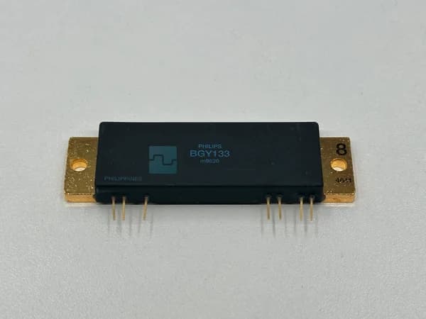
Ready for broadcast and ISM applications requiring high power, integrated matched modules significantly shorten development time. For example Blf278 FM 500 W Amplifier and similar high-power FM stages like Mrf173 160 W FM Amplifier are often preferred in class C/AB FM chains. For lower-power gain blocks that can be easily integrated into systems, Bgy133 RF Power Amplifier and Ca2870 RF Amplifier are good starting points.
 Used in VHF/FM power amplifiers, an LDMOS-based module: Mrf173 160 W Fm Amplifier.
Module or Discrete Transistor?
There are two approaches. An integrated amplifier module, which operates at a specific impedance (usually 50 Ω) and contains matching networks and sometimes multiple stages, is a ready-made block that speeds up design and ensures repeatability. A discrete RF power transistor (bipolar, MOSFET, or LDMOS) gives the engineer the freedom to design the topology, class, and matching from scratch; it is more flexible in cost and performance optimization, but the entire PCB design, matching, and thermal solution are the responsibility of the designer.
In practice, many systems use both together: an integrated driver in the pre-stage and a high-power separate transistor in the final stage. For example, an element such as a 2N6080 RF Transistor can be used to drive a larger final stage transistor. For those who want to take a closer look at the separate element side, the RF transistor category offers bipolar, MOSFET, and LDMOS options together.
From the manufacturer, classic bipolar and modular solutions Philips and Motorola products have been field-proven for many years; for high-power FM broadcast modules, brands like Siel stand out.
Frequently Asked Questions
What is the difference between an RF power amplifier and a small signal amplifier?
The small signal amplifier is designed to provide gain without distortion and has low output power. The RF power amplifier prioritizes output power, efficiency, and thermal reliability; the active element is operated close to saturation in high signal conditions, most of the time.
Which class is suitable for an FM transmitter?
Since FM is a fixed envelope modulation, amplitude linearity is not critical. Therefore, high-efficiency Class C (or well-tuned AB) final stages are the preferred choice. This results in less heat and lower power consumption for the same power.
Why is PAE (power-added efficiency) important?
PAE indicates the percentage of RF power output that is efficiently generated from the DC source, taking into account driving power. High PAE means a smaller power supply, less heat, and lower operating costs. It directly affects the total cost of ownership, especially in continuously operating transmitters.
How can I increase accuracy and efficiency at the same time?
It is not possible to maximize both with a single class; therefore, architectural techniques are used. The Doherty amplifier, envelope tracking, and digital pre-distortion (DPD) provide a practical balance between the two by aligning the switching or Class C efficient stages.
Summary and Next Step
RF power amplifier selection begins by determining the correct operating class based on the nature of the signal (constant envelope or amplitude modulation) and required output power; then it comes down to the frequency band, linearity, PAE, and thermal resistance parameters to decide on the module or discrete transistor; in constant envelope, high-power applications, efficiency-oriented C-switching classes are preferred, while in digitally modulated systems, AB class with linearization support comes to the forefront.
If you want to clarify the suitable solution for your project, review the Kare Dalga RF amplifier catalog and complementary RF transistor options; you can get a quote from our team for the power, band, and package that fit your needs and quickly obtain information about stock and technical compatibility.