
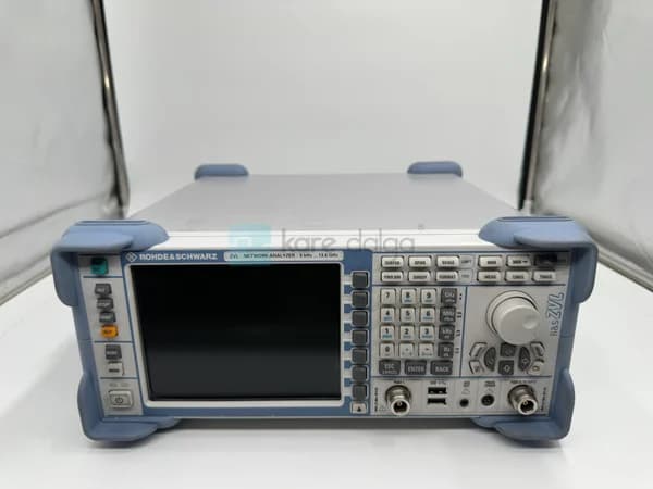
RF Network Analyzer with S-Parameter Measurement
The success of an RF design is often directly proportional to your ability to measure it. Since it is impractical to directly measure voltage and current at high frequencies, engineers often turn to an approach based on the waves entering and reflected from the circuit. This is where the concepts of the network analyzer and the S-parameter come into play. In this article, we will discuss the theory behind vector network analyzer (VNA) and S-parameter measurements in engineering terms, explain why calibration is the heart of the measurement, cover the practical setup steps, and discuss what to look for when characterizing a component. Our goal is to help you obtain reliable and repeatable results, whether you are characterizing an antenna, a filter, or an RF transistor.
What Are S-Parameters and Why Are They Used?
S-parameters (scattering parameters) are complex numbers (containing amplitude and phase) that define the relationship between the power waves entering and reflected from the ports of an RF circuit. Z (impedance) or Y (admittance) parameters, which are used to characterize circuits at low frequencies, require the ports to be open or shorted during measurement. However, it is nearly impossible to achieve ideal open/shorted conditions at high frequencies; in addition, active devices can oscillate under these conditions.
S-parameters measure by terminating the ports in characteristic impedance (usually 50 Ω). This is both physically applicable and a safe method for the device at high frequency. Four basic S-parameters are defined for a two-port network:
- S11 — Input return loss. Indicates the amount of signal reflected back to port 1, which is an indicator of the quality of the match.
- S21 — Forward transmission gain. It defines the signal transmitted from Port 1 to Port 2; it gives the gain in an amplifier and the insertion loss in a filter.
- S12 — Reverse isolation coefficient. Equal to S21 in passive and reciprocal circuits; indicates isolation in active devices.
- S22 — Output return loss. Defines the match at the port 2 side.
With these parameters, you can obtain all critical engineering quantities such as return loss, VSWR, insertion loss, gain, group delay, and phase response with a single measurement. S-parameter files are typically stored in Touchstone (.s2p,.s1p) format and can be directly imported into simulation tools.
What is a Network Analyzer? Scalars vs. Vectors
A Network analyzersare RF test devices that measure the frequency-dependent response of a device or circuit (DUT — Device Under Test). There are two main types:
- Scaler Network Analyzers (SNA): Only measures amplitude (e.g. gain or loss in dB). Since it does not measure phase, it cannot provide quantities such as complex impedance or group delay.
- Vector Network Analyzer (VNA): Measures both amplitude and phase. This enables it to provide a full set of complex S-parameters, display impedance on the Smith chart, and perform error-corrected (calibrated) measurements. The VNA is the standard tool in modern RF engineering.
A VNA consists of a signal source, directional couplers (to separate incoming and reflected waves), and phase-locked receivers. Some devices combine the network analyzer function with spectrum analyzer capabilities, providing a multi-purpose measurement platform in a single box, which is convenient for field teams and those with limited laboratory budgets.
 The Rohde & Schwarz R&S & Black ZVL-13, a practical platform for S-parameter measurements.
Why is VNA Calibration the Heart of Measurement?
The raw measurement of a VNA is filled with systematic errors; cable losses and phase shifts, connector mismatches, finite directivity of directional couplers, and receiver errors. Calibration subtracts these systematic errors from the measurement by fitting them into a mathematical error model. reference plane is transferred to the point where the DUT is connected. The return loss or gain value measured with an uncalibrated VNA can be several decibels off from the actual value.
Common calibration methods include:
- SOLT (Short-Open-Load-Thru): The most common method, using known short circuit, open circuit, 50 Ω load, and straight connection standards. Ideal for connector-based measurements.
- TRL (Thru-Reflect-Line): Preferred for connectorless fixtures and PCB measurements; based on transmission lines.
- Electronic Calibration (e-cal): Provides fast and operator-error-free calibration with a single automatic module.
The Golden Rule: Perform calibration on the exact plane where the DUT will be connected, at the frequency range and power level you will use. Moving cables or adding adapters after calibration will distort the reference plane and invalidate the measurement.
How to Perform S-Parameter Measurements Step by Step?
The basic flow to follow for a practical two-port S-parameter measurement is as follows:
- Determine the frequency range and number of points. Scan only the band of interest; unnecessary wide scanning resolution reduces accuracy. Increase the number of points for sharp filter responses.
- Set the source power. Typical values are suitable for passive devices; avoid compression by keeping the power low to stay in the linear region in an active device (e.g., amplifier or transistor).
- Select the IF bandwidth. A narrow IF bandwidth reduces the noise floor and increases dynamic range, but increases sweep time. A narrow IFBW is required for high isolation measurements.
- Perform calibration. Complete full two-port calibration with the standards appropriate to the method you have chosen.
- Connect the DUT and measure. Tighten the connectors with controlled torque; loose connections can cause phase instability and incorrect S11/S22.
- Verify and record the result. Examine the Smith chart and the dB format, and export as a Touchstone file.
Which Components Are Characterized Using the S-Parameter?
S-parameter measurement covers a wide range of passive and active components: antennas, filters, couplers, attenuators, cables, and especially active RF devices. A RF transistor or in amplifier design, S-parameters are indispensable for understanding the device's gain, input/output matching, and stability. For example 2N6080 RF transistor on a circuit, it is essential to understand the S21 and S11 behavior. Similarly, for 2SC2510 and BFQ34, can only be reliably compared using VNA measurements. A critical nuance here is that the S-parameters of active devices depend on their operating point (DC bias) and input power level. The typical S-parameter sets given in the datasheet are valid for a specific bias and frequency; if your actual design conditions are different, the most accurate approach is to remeasure the device in your own setup.
 The active RF component, the 2N6080 RF transistor, is characterized on a VNA with its S-parameters, which are dependent on the bias voltage and power level.
In passive components, the situation is simpler: since a filter or attenuator is linear and reciprocal, S12 is equal to S21, and the measurement is valid at a single operating point. In active devices, however, quantities such as gain, stability, and noise figure must be reported in conjunction with the measurement conditions; otherwise, results from different laboratories cannot be compared.
Comparison of VNA Measurement Parameters
The following table summarizes the meaning of the parameters commonly encountered in S-parameter measurements and the corresponding engineering quantities:
| S-Parameter | Definition | Derived Quantity | Ideal Direction |
|---|---|---|---|
| S11 | Input reflection | Return loss, VSWR, input impedance | As low as possible (good match) |
| S21 | Forward transmission | Gain (active) / Insertion loss (passive) | High in amplifier, high in filter band |
| S12 | Reverse transmission | Isolation, feedback | Low in active device (high isolation) |
| S22 | Output reflection | Output return loss, output impedance | As low as possible (good match) |
To interpret the values shown in the table correctly, it is critical that the measurement device has a dynamic range and directivity that are appropriate for the level you are measuring. To accurately measure the S12 of a high-isolation device, your device's noise floor must be sufficiently below the level you are measuring. In practice, the most effective way to extend the dynamic range is to narrow the IF bandwidth and, if necessary, take an average; the price is a longer sweep time.
 Elements such as the 2SC2510 RF transistor have different gain profiles, but can be objectively compared with consistent VNA measurements.
Finally, do not underestimate measurement uncertainty. Factors such as connector repeatability, cable twisting, and temperature drift add significant uncertainty to the results, especially in low return loss (e.g., below -20 dB) measurements. Using a torque switch and thermally balancing the instrument significantly increases repeatability.
Frequently Asked Questions
Is the Skaler analyzer a S-parameter meter?
The Skaler network analyzer measures only amplitude information, it cannot measure phase information. Therefore, it can provide amplitude quantities such as |S21| and |S11| but is insufficient for full characterization based on complex impedance, group delay, or Smith chart. A vector network analyzer (VNA) is required for a complete set of S-parameters.
How often should the VNA be calibrated?
Calibration becomes invalid with changes in temperature, cable or adapter changes, or when the test setup is changed. In practice, it is safest to re-calibrate after each new measurement session and when the test setup changes. In long measurements, drift can be controlled with periodic verification standards (e.g., a known thru).
How do I transfer the S-parameter file to simulation?
VNA exports the measurement result in Touchstone format (for two ports,.s2p). This file contains amplitude and phase versus frequency and can be loaded directly into RF/circuit simulators as a "black box" model. This allows the actual device behavior measured to be used directly in the design environment.
Can measurements be made with a different reference impedance instead of 50 Ω?
The measurement hardware operates with a 50 Ω (75 Ω in some video/CATV applications) reference, but the measured S-parameters can be mathematically converted to another reference impedance (renormalization). Most VNA software provides this conversion natively, allowing you to analyze according to different system impedances.
Conclusion: Reliable RF Characterization with the Right Device
The S-parameter measurement is the fundamental language of RF design, expressing the compliance, gain, isolation, and phase behavior of a component in a single, consistent framework. The quality of this measurement depends on two things: proper calibration discipline and a vector network analyzer with sufficient dynamic range. Rohde & Black and other established brands offer VNA and spectrum analyzer solutions that deliver repeatable results in both laboratory and field measurements.
in the square wave catalog RF network analyzers as well as the devices you will measure and characterize RF transistor. Choosing the right device when setting up your test and measurement infrastructure affects your project throughout its entire lifecycle. Explore our categories for network analyzers or RF components that meet your needs, and get a quote from our technical team.