
MOSFET and LDMOS RF Transistors: Comparative Guide
For an RF power amplifier designer, the choice of active device determines everything from the efficiency of the circuit to its linearity, thermal behavior, and cost. RF MOSFET and LDMOS (Laterally Diffused MOS) technologies are the two approaches at the center of this decision. Although both belong to the field-effect transistor (FET) family, their structural architectures, frequency behaviors, and power scales are distinctly different. In this guide we will compare LDMOS vs MOSFET from an engineering perspective; discussing which one comes out on top in which application and why, the selection criteria, and their relationship to classic bipolar RF transistors. The goal is to enable you to read the right parameters in the right context when looking at a datasheet.
An overview of RF transistor technologies
There are three main generations of RF power amplification technologies: bipolar junction transistors (BJTs), conventional RF MOSFETs, and LDMOS structures. More recent GaN (gallium nitride) solutions are positioned as the fourth generation. Within this range, MOSFETs and LDMOS, due to their silicon-based nature, still dominate a very wide range of applications in terms of cost/performance balance.
Classic bipolar RF transistors — such as the 2SC2510 and 2SC2782 in our catalog — are current-controlled devices and require careful polarization (bias) due to their thermal runaway tendency. FET-based structures, on the other hand, offer a natural current balancing advantage in parallel operation and wide-area dies due to their voltage-controlled nature and the increase in channel resistance with temperature. This is the main reason for the rise of MOS technologies in the RF power world. You can explore all relevant active components under the RF transistor category can be reviewed below.
To properly frame your technology choice, it is important to understand two concepts. The first is power density: how much RF power you can draw from the same die area, which determines both cost and in-package thermal density. The second is linearity: how closely the signal at the amplifier output follows the input signal. While linearity is secondary in fixed-envelope modulation (such as analog FM), in modern digital waveforms (OFDM, QAM) linearity is critical due to high peak-to-average power ratio (PAPR). The choice between MOSFET and LDMOS is largely driven by your requirements along these two axes.
 The transistor packages used in RF power stages; heat transfer and flange design performance directly affect. BFQ34 for example.
What is an RF MOSFET and how does it work?
RF MOSFET is a field-effect transistor that controls the channel conductivity between the gate voltage and the source and drain, and can be manufactured in a vertical or horizontal configuration. In the conventional VDMOS (Vertical Diffused MOS) structure, current flows vertically from the top surface of the die to the bottom surface, which facilitates the achievement of high breakdown voltages.
The key advantages of RF MOSFETs include:
- High input impedance: The gate is capacitively driven; it does not require a continuous base current. This simplifies the driver solid-state design.
- Negative temperature coefficient: Since channel resistance increases with temperature, current avoids hot areas, providing automatic balancing in parallel die cells.
- Fast switching: It is superior to switching (Class D/E/F) applications because there is no minority carrier storage delay.
Conventional RF MOSFETs are particularly prevalent in the HF/VHF band, in applications such as FM broadcasting and industrial heating. A notable example in this class is the BLF177, a MOS structure that provides high power in the VHF band and is often preferred in FM transmitter stages.
What is LDMOS and what is the difference from the conventional MOSFET?
LDMOS (Laterally Diffused Metal-Oxide-Semiconductor), as the name suggests, the current flows along the die surface vertical is a variant of MOS. It has an asymmetric channel, created by "lateral diffusion" under the gate, and a long, lightly doped drift region. This drift region allows the channel to remain short while safely carrying high drain voltages — i.e., both high breakdown voltages and low on-resistance (RDS(on)) is obtained together.
The main features that make LDMOS the standard of the modern RF power world:
- Low return flow capacity (Crss): The source metallization is connected below the die (source-down design), which reduces the return flow through the passage and provides high gain and stability.
- Excellent thermal path: The source-down design facilitates the transfer of heat directly to the flange.
- High linearity: Offers the critical low intermodulation distortion for modern communication waveforms (LTE, 5G, DVB).
- Scalable power: Hundreds of watts of RF power in a single package is common in base stations and broadcast transmitters.
To expand the functionality of the drift region a bit further, the high drain voltage falls to this lightly doped long region instead of the channel. This allows the channel to be kept very short, resulting in low on-resistance and high transconductance. At the same time, the high breakdown voltage is preserved. This "two in one" balance is a design advantage that is much harder to achieve in traditional vertical structures, and is the basis for the preference of LDMOS for advanced amplifier topologies such as the high-efficiency Doherty architecture.
In summary, although LDMOS is a subclass of the traditional vertical MOSFET, its horizontal architecture clearly sets it apart in the high frequency + high power + high linearity triangle. However, it should be kept in mind that at very high frequencies (several GHz and above), silicon LDMOS also approaches its physical limits, and here materials with a wide band gap, such as GaN, come into play.
 VHF band high power MOS transistor BLF177; used in broadcast and industrial RF applications.
LDMOS vs MOSFET: in which parameters do they differ?
When we put these two technologies side by side, the difference is not a single "winner," but rather a balance sheet that varies depending on the application. The comparison below summarizes which headings to focus on when reading the datasheet.
| Feature | Traditional RF MOSFET (VDMOS) | LDMOS |
|---|---|---|
| Current direction | Vertical | Horizontal (lateral) + drift zone |
| Typical frequency range | HF – VHF (common), some models UHF | VHF – UHF, microwave sub-bands |
| Power density | Medium-high | Very high (hundreds of W per package) |
| Linearity/IMD | Good | Very good (suitable for modulated signals) |
| Thermal behavior | Negative temperature coefficient | Negative coefficient + source-down heat path |
| Replay Capacity | Highly Visible | Low (High Gain/Stability) |
| Typical applications | FM broadcasting, RF heating, switching | Base station, TV/FM transmitter, radar |
The table highlights the following: both FETs share the benefits of voltage control and thermal stability that come with being FETs. The breakdown is due to the LDMOS's drift region architecture, which allows it to offer both high-frequency linearity and power density. In contrast, conventional MOSFETs are still competitive in terms of cost for lower-frequency high-power and switching applications.
How to choose the correct RF transistor?
To systematize the selection process, we recommend that you follow the steps below. This approach is useful both in new designs and in the modernization of an aging transmitter board.
- Frequency band: If the operating frequency fT is very close to the gain-bandwidth limits, it is better to move up a class rather than pushing the technology to its limits. LDMOS is a strong candidate for UHF and above.
- Output power and class: The target power should be well below the saturation power (Psat). For switchable efficiency, consider Class D/E/F MOSFETs for linear modulation, LDMOS for non-linear modulation.
- Linearity requirement: Linearity is secondary in a constant envelope signal (FM); in a modulated signal (QAM/OFDM), IMD and ACPR are critical — this is a criterion in favor of LDMOS.
- Supply voltage: LDMOS typically operates at high drain voltages (e.g., 28–50 V class); verify compatibility with your existing power supply infrastructure.
- Thermal design: Size the junction-to-case thermal resistance (RθJC) and flange mounting according to your cooling capacity.
- Supply and Equivalent: To find a functional equivalent in legacy/obsolete parts, consider pinout, package, and RF parameters together.
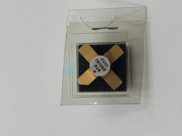
Our catalog features a wide range of products, from classic bipolar references (2N6080) to high-power MOS-based solutions. If you would like to browse by brand, you can view Philips, Motorola and Toshiba RF transistors.
 Classic 2N6080 RF power transistor; a frequently sought reference in the maintenance of old designs.
Frequently Asked Questions
Is LDMOS a MOSFET?
Yes. LDMOS is a sub-type of the MOSFET family; the MOS in "Laterally Diffused MOS" refers to the metal-oxide-semiconductor gate structure. The difference is that the current flows horizontally along the die surface and has a separate drift region that carries high voltage. This structure provides better gain and linearity at high frequencies compared to conventional vertical MOSFETs.
What are the benefits of using LDMOS instead of MOSFET in RF power amplification?
The most significant benefits are higher gain and stability due to lower feedback capacitance, better thermal performance due to the source-down structure, and superior linearity in modulated signals. LDMOS offers significant advantages, especially in the UHF band and in amplifiers that require hundreds of watts of power. In low-frequency or switching applications, however, conventional MOSFETs can still be cost-effective.
Can I directly replace my old bipolar RF transistor with a MOSFET?
A direct one-to-one replacement is usually not possible. Bipolar transistors are current-controlled, while FETs are voltage-controlled; the bias circuit, driver stage, and matching network must be redesigned. Even if the pinout and package appear to be compatible, the bias and stability conditions are different. It is essential to compare the datasheet parameters and application notes before making a replacement.
Which technology is more suitable for an FM transmitter?
Since FM is a constant-envelope modulation, linearity is not critical; therefore, both high-power traditional RF MOSFETs and LDMOS structures are widely used. In VHF FM broadcasting, BLF177 like high-power MOS transistors are a classic choice. As the power scale increases and efficiency becomes a priority, LDMOS becomes more advantageous.
Summary and Next Step
MOSFET and LDMOS are two technologies that share the same FET base but have different architectural priorities. Traditional RF MOSFETs require simple drive, thermal stability, and switching speed. LDMOS, on the other hand, has become the backbone of modern transceiver and base station designs by combining high frequency, high power density, and superior linearity with its horizontal drift architecture. The right choice is clear after considering frequency, output power, linearity, supply voltage, and thermal budget together.
When selecting the suitable RF active component for your project, you can take advantage of the current stock and equivalent options in the Square Wave catalog. You can view all models in our RF transistor category; you can request a quote from our team for technical specifications or one-to-one/equivalent part procurement. Matching the right component to the right application reduces both design risk and total cost. Correctly pairing the component with the application lowers both design risk and total cost