
What is an RF Transistor? Types and Selection Criteria
At the heart of RF circuits, there is a single active element that amplifies and shapes the signal: the RF transistor. From low-noise preamplifiers on the transmitter output stages to FM broadcast amplifiers to military communications modules, choosing the right transistor for each application directly determines the gain, efficiency, and accuracy of the design. In this guide, we take a technical look at what an RF transistor is, what types are available, and which parameters on the data sheet you should look for as a designer. Our goal is to clear up any questions you may have about choosing the right rf transistor and help you confidently select the right component for your application.
What is an RF Transistor and How Does it Differ from an Ordinary Transistor?
RF transistors are semiconductor amplification devices optimized to operate in the radio frequency (RF) band, ranging from hundreds of kHz to GHz. The key difference from low-frequency switching or audio transistors is that the parasitic capacitance and inductance are minimized so as not to degrade the signal at high frequencies. RF transistors are typically manufactured with smaller chip geometries, optimized multi-emitter finger structures, and low-inductance packages.
There are two critical frequencies that determine the performance of an RF transistor: the unit gain frequency (fT in terms of transition frequency) and the maximum oscillation frequency (fmax). In practice, you want to select a transistor so that its operating frequency is well below fT; otherwise, the gain will drop rapidly and the circuit will become unstable. Therefore, being "fast enough" is more important than the highest frequency number on the data sheet when selecting an RF transistor.
Another distinguishing feature is that RF transistors live in the world of impedances. In a low-frequency circuit, you can connect a transistor directly to a source and a load; in RF, however, the input and output impedances change with frequency, so an impedance matching network is almost always required. Manufacturers therefore typically specify the large signal input/output impedances or S-parameters at a particular frequency on their data sheets. A well-designed matching network directly determines the power, efficiency, and stability that can be extracted from the transistor; therefore, transistor selection and circuit topology cannot be considered separately.
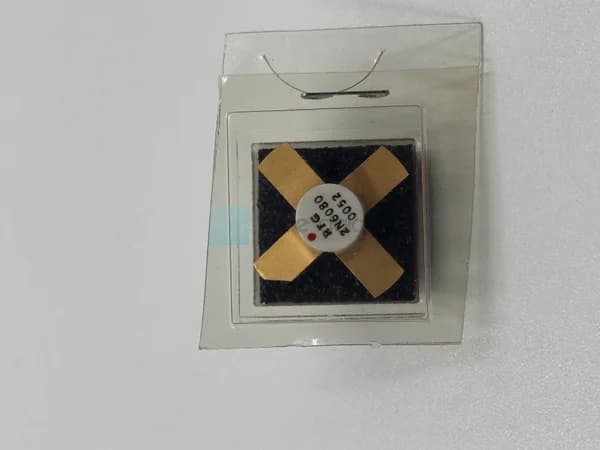
 VHF band transmitters commonly use 2N6080 RF transistors and other bipolar power devices, which are the backbone of traditional communication designs.
What are the Types of RF Transistors?
RF transistors are divided into several main groups based on the semiconductor technology they use and their operating principle. Each technology has its own gain, noise, power, and frequency advantages; the correct choice is determined by the balance required by the application.
Bipolar Junction Transistor (BJT / RF Bipolar)
Classic silicon bipolar RF transistors have been the basis of transmitter output stages and driver stages in HF, VHF, and UHF bands for decades. They are preferred, especially in broadcast and communication applications, due to their high current gain and relatively low cost. Bipolar transistors such as 2SC2510 and 2SC2782 from Toshiba in our catalog are typical examples of this class and frequently appear in VHF/UHF driver stages.
RF MOSFET and LDMOS
Field-effect (FET) RF transistors offer high input impedance and good linearity due to their gate voltage-controlled structure. In particular, Lateral Diffused MOS (LDMOS) technology has become the industry standard for high-power FM and TV broadcast amplifiers. Philips produces BLF177, a powerful MOS RF transistor example designed for high-power VHF push-pull stages.
Low-Noise and Small-Signal RF Transistors
In receiver preamplifiers (LNA) where the signal is still very weak, any additional decibel of noise degrades the overall system noise figure. At these stages, low noise figure (NF) small signal transistors are used. BFW16A and BFQ34 are good examples of this category, with structures optimized for small signal and driver applications.
GaAs and GaN Technologies
Compounds such as gallium arsenide (GaAs) and gallium nitride (GaN) provide performance at microwave and millimeter-wave frequencies that silicon cannot match. GaN is particularly well suited for radar and base station applications that require high power density, high operating voltages, and excellent thermal conductivity. Because these technologies are expensive, they are typically used only in high-frequency or high-power applications where silicon is not sufficient.
What Parameters Should Be Considered When Selecting an RF Transistor?
Choosing the right RF transistor involves establishing a conscious balance between the requirements of the application and the data sheet parameters, rather than simply searching for the "best" part. The following criteria are the key considerations that guide your engineering decisions:
- The operating frequency (fT /fmax): ) offered by the gain of the transistor should comfortably cover your target band. As a general rule, the operating frequency is required to be significantly below fTshould be significantly below
- Output power (Pout): Continuous (CW) or pulsed power withstand capability is critical for the output stages. It is important not to confuse the power transistor with the small signal transistor.
- Power gain (Gain): The gain in dB at a given frequency determines how many stages are required.
- Noise figure (NF): Low NF at the receiver front ends directly affects the system's sensitivity.
- Accuracy (IP3, ACPR): It limits sideband distortion and intermodulation in modulated signals, which is especially important in digital communications.
- Supply voltage and current: Architectural choices such as 12.5 V, 28 V, or 50 V affect both performance and thermal design.
- Thermal resistance (RthJC) and package: Heat dissipation is one of the most critical factors determining the reliability of power transistors.
 For high-power broadcast applications BLF177 like MOS-based RF power transistors, linearity and heat management should be carefully considered.
Comparison of RF Transistor Types
The following table summarizes the main RF transistor technologies with their typical characteristics and application areas. These general trends are indicative when choosing a technology instead of a specific part.
| Technology | Typical Frequency | Power Level | Feature Highlight | Typical Application |
|---|---|---|---|---|
| Bipolar (BJT) | HF–UHF | Medium–High | High gain, low cost | Broadcast, communication transmitters |
| RF MOSFET | HF–VHF | Mid-range | High input impedance | Driver and switching stages |
| LDMOS | VHF–UHF | High | Accuracy + high power | FM/TV broadcast amplifiers, base station |
| GaAs | UHF–mmW | Low–Medium | Low noise, high frequency | LNA, microwave front ends |
| GaN | UHF–mmW | Ultra High | High power density | Radar, defense, base station |
How to Choose the Right RF Transistor for Your Application?
In practice, the selection process begins with clarifying what your application expects from the transistor. For a rf power transistor, you want high power handling, efficiency, and thermal management at the transmitter output stage; at the receiver input stage, you want low noise figure and stability. Similarly, a narrowband CW application and a wideband modulation system have very different linearity requirements.
The second step is to determine the package and thermal solution suitable for your existing power supply architecture and mechanical constraints. While high-power flanged (bolt-down) packages are preferred, surface mount or classic metal box packages may be sufficient for low power. Keeping the junction temperature of power transistors below safe limits is often the single most critical factor determining the element's lifespan; therefore, thermal resistance value, cooler selection, and mounting surface flatness should be considered at the beginning of the design. Established manufacturers like and Keysight have classic RF transistors that are still sought-after parts in maintenance and repair of decades-old designs; thus, finding compatible equivalents is also part of the selection.
Thirdly, stability is a frequently overlooked but decisive criterion. A high-gain transistor can enter unwanted oscillations at inappropriate source/load impedances. Designers assess this risk with metrics such as the Rollet stability factor (K) and guarantee unconditional stability with small resistors or feedback networks when necessary. Skipping this control, especially in wideband amplifiers, prevents many faults encountered in the field.
At Kare Dalga, in the RF transistor category, we have a wide range of products in our catalog, from bipolar power transistors to MOS-based high-power devices, and small signal and driver transistors. This makes it easier for you to find the right component for both your current projects and older equipment that requires maintenance.
 For driver and small signal stages, BFQ34 and similar components, they play a critical role in ensuring gain and noise balance.
Frequently Asked Questions
What is the difference between an RF transistor and a normal transistor?
The key difference is that parasitic capacitances and inductances are minimized to the point where they will not affect the high-frequency signal. RF transistors have transition frequencies extending into the GHz range, optimized chip geometry, and low-inductance packages. Regular transistors, on the other hand, are designed for low frequency or switching and their gain rapidly decreases at RF.
Why are LDMOS transistors preferred in FM broadcast amplifiers?
LDMOS technology combines high power capability with good linearity and robust thermal performance, allowing the modulated broadcast signal to be amplified to high power with low adjacent band distortion. Additionally, its structure suitable for push-pull architectures makes it easy to build high-efficiency VHF/UHF output stages.
How can I find a replacement for the RF transistor in an old device?
First, determine the original part's operating frequency, output power, supply voltage, and package type from the data sheet. Then, find an equivalent with the same basic parameters and pinout/package layout. The square wave catalog's classic Motorola, Toshiba, and Philips transistors are popular compatible options frequently sought after for maintenance of older systems.
Why is noise figure important in RF transistor selection?
Noise figure (NF) is particularly decisive in the first stage of the receiver chain, as the noise added in this stage limits the overall system sensitivity. Using a low-NF transistor when amplifying a weak signal preserves the signal-to-noise ratio. In power output stages, however, power and linearity take precedence over NF.
Summary and Next Step
RF transistor selection is an engineering-based decision that considers frequency of operation, power level, noise figure, linearity, and thermal design all at once. By matching the right technology (bipolar, MOSFET/LDMOS, GaAs or GaN) to your application's requirements, you ensure both performance and reliability. Identifying the correct component for the transmitter output stage, driver stage, or receiver preamplifier simplifies all subsequent design steps.
Looking for the right RF transistor for your project? Browse our range of products in the RF transistor category; if you are unsure about the suitable model for your needs, please contact us to get a quote and suitability support from our technical team.